Electronics are everywhere, silently humming with signals that power our world. But what if you need a very specific signal—a unique pulse, a custom oscillation, or a tailored rhythm for your circuit? That’s where using waveform generators & tutorials comes in. These indispensable tools allow engineers, hobbyists, and educators to craft the electrical “heartbeats” that drive everything from simple blinking LEDs to complex communication systems.
Think of a waveform generator as a digital orchestra conductor, capable of directing electrical currents into precise, reproducible patterns. Whether you're debugging a circuit, testing components, or simply exploring the fundamentals of electronics, understanding how to generate and manipulate these waveforms is a foundational skill.
At a Glance: Your Waveform Generation Toolkit
- Waveform Generators are electronic circuits producing repeatable signals like sine, square, triangle, and sawtooth waves.
- Simple DIY Generators often rely on astable multivibrators, which are relaxation oscillators.
- Schmitt Trigger Inverters (like the TTL 74LS14 or CMOS 40106B) offer an easy way to build basic square wave generators, leveraging their unique "hysteresis" property.
- CMOS versions (e.g., 40106B) generally outperform TTL for DIY generators, providing cleaner signals and greater flexibility in component choice.
- NAND Gate Circuits can also create versatile RC relaxation oscillators, with a "ring of three" configuration offering improved stability.
- Ring Oscillators built from an odd number of logic NOT gates produce very high-frequency signals but are often too unstable for practical, precise applications.
- Arduino Due leverages its Digital-to-Analog Converter (DAC) to create software-defined waveforms, offering an accessible path to more complex signal generation with programmatic control over shape and frequency.
- Key components for DIY generators include resistors (R) and capacitors (C) for timing, along with basic logic gates or Schmitt inverters.
- Frequency control can be achieved by adjusting R and C values, or programmatically with microcontrollers like the Arduino Due.
The Heartbeat of Electronics: What is a Waveform Generator?
At its core, a waveform generator is an electronic circuit designed to produce a repetitive, oscillating electrical signal. These signals, or "waveforms," come in various shapes—sinusoidal (smooth waves), square (sharp on/off pulses), triangular (linear ramps), and sawtooth (quick rise, slow fall, or vice-versa). They are the fundamental building blocks for testing, stimulating, and controlling other electronic components and systems.
Historically, these generators relied on intricate arrangements of oscillators and pulsed circuits, often using basic integrated circuits (ICs) or operational amplifiers connected to resistor-capacitor (RC) tank circuits or quartz crystals for precise timing. Today, their applications span from simple clock signals in digital circuits to complex modulated signals in telecommunications. To truly learn about waveform generators and their diverse forms, it's helpful to understand the principles behind them.
DIY Waveform Generators: Crafting Signals from Scratch
While commercial waveform generators offer immense precision and features, building your own can be incredibly educational and surprisingly effective for many applications. It’s a fantastic way to grasp the interplay of basic electronic components.
Astable Multivibrators: The Foundation of Digital Waves
One of the simplest and most common ways to generate a continuous, square wave output is using an astable multivibrator. This type of relaxation oscillator continuously switches between two unstable states at a steady repetition rate. The result? A consistent square wave, often with a 1:1 mark-space ratio (meaning the "ON" and "OFF" times are equal). These circuits are ideal as digital waveform generators and can be constructed using standard TTL and CMOS logic circuits paired with discrete timing components like resistors and capacitors.
The Simplicity of Schmitt Trigger Waveform Generators
When it comes to ease of construction for a basic astable waveform generator, circuits built around Schmitt trigger action inverters are hard to beat. Chips like the TTL 74LS14 or the CMOS 40106B are specifically designed with "hysteresis"—they change state at different input voltage levels (an upper threshold to "set" the output, and a lower threshold to "reset" it). This characteristic is crucial, as it ensures stable waveforms that switch quickly and cleanly between "HIGH" and "LOW" states without unwanted distortion or noise.
The TTL 74LS14 Schmitt Inverter Generator
Imagine a single TTL 74LS14 Schmitt inverter, a capacitor (C) connected between its input and ground, and a feedback resistor (R) running from its output back to its input. That's the core of this simple oscillator.
- How it Works:
- When the capacitor's charge is below the lower threshold (e.g., 0.8V for TTL), the inverter's output is logic "1" (+5V).
- This +5V output charges the capacitor through the feedback resistor R.
- As the capacitor charges, its voltage rises. Once it reaches the upper threshold (e.g., 1.6V), the inverter's output rapidly switches to logic "0" (0V).
- Now, the capacitor discharges through the same resistor R.
- When the capacitor's voltage drops back down to the lower threshold (0.8V), the output switches back to logic "1."
- This cycle repeats, creating a continuous square wave.
- Output Characteristics: Due to the internal characteristics of TTL input gates, the output waveform from a 74LS14 often isn't a perfect 50% duty cycle. Instead, you'll typically see an asymmetrical waveform with a duty cycle of approximately 33%, or a 1:2 mark-to-space ratio.
- Frequency Control: The frequency of oscillation is directly controlled by the values of R and C. The formula is approximately:
f = 1 / (0.8 * R * C). - Component Values: For stable operation, the feedback resistor R usually needs to be kept quite low, often below 1kΩ (220Ω to 470Ω is a common recommendation). With R between 100Ω and 1kΩ and C ranging from 1nF to 1000uF, you can achieve frequencies from 1Hz up to 1MHz.
- Limitations: While straightforward, standard TTL gates aren't always ideal. They can suffer from waveform distortion at higher frequencies (turning square waves into trapezoids) and require low feedback resistors, which means you need larger—and often more expensive—capacitors for low-frequency applications. Sometimes, if the feedback capacitor is too small, the circuit may even fail to oscillate.
The CMOS 40106B Schmitt Inverter Generator: An Upgrade
For better performance, especially in terms of noise immunity and waveform quality, CMOS logic offers a significant advantage. The CMOS 40106B Schmitt Inverter, for example, operates over a wider voltage range (3V to 15V) and provides a "squarer" output waveform.
- Advantages: CMOS devices boast high bandwidth, high gain, and excellent input/output characteristics, leading to cleaner, more stable signals.
- Circuit Improvement: While similar to the TTL version, a common modification for the CMOS 40106B circuit includes a 10kΩ resistor in series with the feedback resistor to protect the sensitive MOSFET input transistors during rapid capacitor discharge at higher frequencies.
- Output: Expect a more symmetrical output waveform, closer to a 1:1 mark-space ratio.
- Frequency Control: With CMOS, you can use larger feedback resistors (up to 100kΩ), which allows for smaller and more cost-effective timing capacitors. This expands your practical frequency range, typically from 0.1Hz to 100kHz with R between 1kΩ and 100kΩ and C between 1pF and 100uF. The exact frequency formula might differ slightly from the TTL version but remains inversely proportional to R and C.
Practical Hacks for Your Schmitt Generator
These simple circuits are surprisingly versatile. Here are a few ways to enhance them:
- Complementary Outputs: Need both an ON and an OFF signal at the same time? By feeding the output of your first Schmitt inverter into a second Schmitt inverter, you get a clean, inverted version of your original waveform. This gives you two complementary outputs, with only a tiny delay between them.
- Variable Frequency: Replace the fixed feedback resistor R with a potentiometer (a variable resistor). This allows you to dial in your desired frequency on the fly. Just remember to keep a small fixed resistor in series with the potentiometer to prevent it from shorting out the circuit at its lowest resistance setting.
- LED Flashing: The complementary outputs are perfect for driving switching transistors, which can then alternately flash LEDs. Just make sure to include a series resistor for each LED to limit the current to below 20mA.
- Frequency Division: For very low frequencies (think a few Hertz) without needing massive, expensive capacitors, generate a higher frequency (e.g., 1kHz or 10kHz) and then use ripple counters. These are cascaded divide-by-2 D-type flip-flops (like the CMOS 4024 or 4040) that can divide your clock frequency into sub-frequencies (ƒ÷2, ƒ÷4, ƒ÷8, and so on).
NAND Gate Waveform Generators: Versatile Logic Circuits
You can also create functional waveform generators using standard CMOS Logic NAND Gates, configured to act as inverters. These circuits are another common way to build RC relaxation oscillators.
Two-Gate Circuit
This setup uses two NAND gates. An RC network (R1 and C) is controlled by the output of the first NAND gate. Feedback from the output of the second NAND gate (configured as an inverter) is then routed back to the input of the first NAND gate through a resistor (R2). Oscillation occurs as the capacitor charges and discharges between the NAND gates' threshold levels.
- Frequency:
f = 1 / (2.2 * R1 * C) - Component Relationship: R2 is typically chosen to be about 10 times the value of R1.
Three-Gate Circuit ("Ring of Three")
Using three inverting NAND gates (or any three logic inverters) connected in a ring offers improved stability and ensures that the oscillator starts reliably, even with very low capacitor values. This configuration is also less susceptible to power supply variations because its switching threshold is very close to half the supply voltage.
- Output: This circuit produces a nearly 50% duty cycle (1:1 mark-space ratio), providing a symmetrical square wave.
- Frequency: The frequency formula is similar:
f = 1 / (2.2 * R1 * C), with R2 still typically 10 times R1. - Trade-off: The main disadvantage is that it uses an additional logic gate compared to the two-gate version.
Ring Oscillators: High-Frequency, Low-Control
A truly minimalist approach to oscillation is the "ring type waveform generator." This circuit is constructed using only an odd number of logic NOT gates (inverters)—3, 5, 7, 9, etc.—connected in a closed loop, with the output of the last gate fed back into the input of the first.
- How it Works: A logic "1" (or "0") introduced into the ring continuously propagates through each inverter, flipping its state as it goes. Because there's an odd number of inversions, the signal effectively chases itself around the ring, creating a continuous oscillation.
- Frequency: The frequency of this oscillation is determined by the total propagation delay of the inverters within the ring. Propagation delay (Tp) is the tiny amount of time it takes for a signal to pass through a single inverter. The frequency is calculated as:
f = 1 / (2 * n * Tp), wherefis frequency,nis the number of gates, andTpis the propagation delay per gate. - Example: If you use five inverters, each with an 8ns (nanosecond) propagation delay, your frequency would be
1 / (2 * 5 * 8ns) = 1 / (80ns) = 12.5MHz. - Practicality: While fascinating, ring oscillators are generally impractical for most applications. They are inherently unstable and tend to oscillate at very high frequencies (tens of Megahertz), making them difficult to control precisely. For more accurate and controllable astable relaxation oscillators, adding RC networks across inverter circuits is the preferred method.
Leveraging Arduino for Advanced Waveform Generation
Moving beyond purely analog or simple logic-based circuits, microcontrollers like the Arduino Due open up a world of possibilities for generating more complex and programmable waveforms.
The Arduino Due as a DAC-Powered Signal Source
The Arduino Due board stands out because it features built-in Digital-to-Analog Converters (DACs). This means it can take a digital value (a number) and convert it into a corresponding analog voltage, making it perfect for creating custom waveforms.
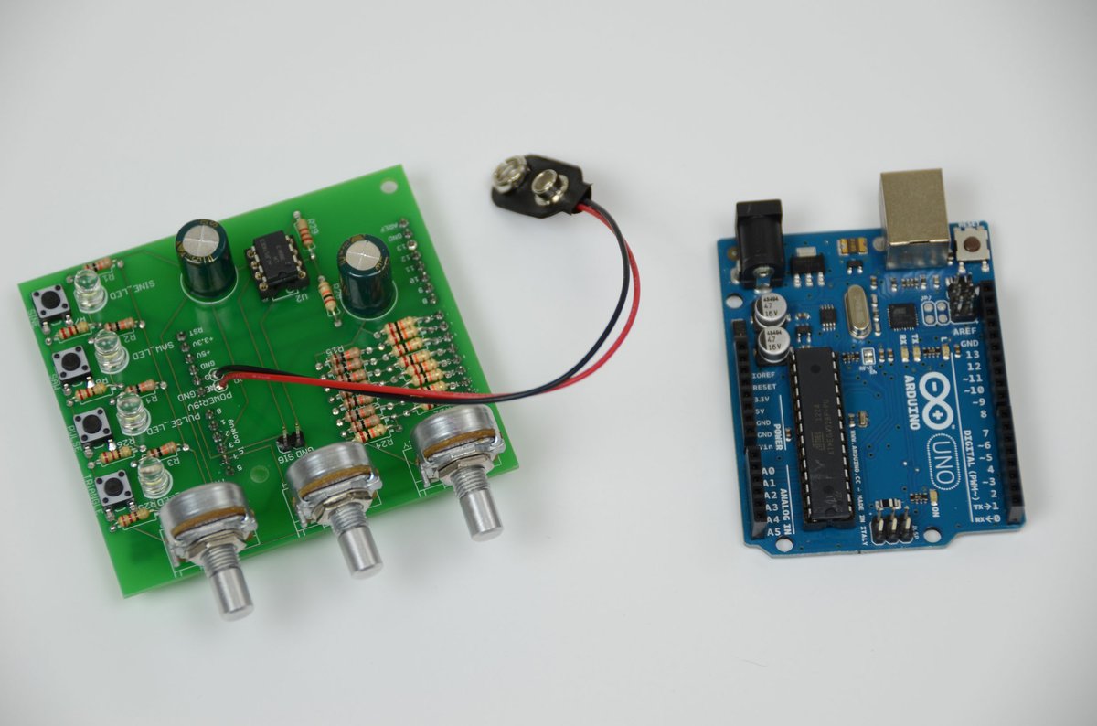
- Purpose: The Arduino Due can become a simple, yet powerful, waveform generator capable of producing sine, triangular, sawtooth, and square waves.
- Functionality: You can select your desired waveform shape using push buttons and precisely adjust the signal frequency using a potentiometer. The generated waveform is then output through its DAC0 and DAC1 channels, ready for visualization on an oscilloscope or input into another circuit.
Building Your Arduino Due Waveform Generator
Getting started with the Arduino Due is a relatively straightforward process, combining basic circuit assembly with programming.
Hardware Required:
To build this setup, you'll need a few common components:
- Arduino Due board
- 10 KΩ potentiometer
- 2 push buttons
- 2 10 KΩ resistors (for pull-down)
- Jumper wires
- Breadboard
- Arduino IDE (online or offline)
- Oscilloscope (highly recommended for visualizing your creations!)
Step-by-Step Circuit Assembly:
- Power Distribution: Connect the Arduino's 3.3V power output and ground (GND) to the power rails of your breadboard. This provides a convenient power source for your components.
- Push Button 1 (Waveform Select):
- Connect one leg of the push button to Arduino digital pin 2.
- Connect the same leg to ground via a 10 KΩ pull-down resistor. This ensures the pin reads LOW when the button isn't pressed.
- Connect the other leg of the push button to the 3.3V power rail.
- (When pressed, the button connects pin 2 to 3.3V, registering a HIGH signal.)
- Push Button 2 (Channel 2 Waveform Select): Wire this button identically to Push Button 1, but connect its signal leg to Arduino digital pin 3.
- Potentiometer (Frequency Control):
- Connect one outer leg of the potentiometer to 3.3V.
- Connect the other outer leg to ground.
- Connect the middle pin (wiper) of the potentiometer to Arduino analog input A0.
- (Turning the pot will vary the voltage at A0 between 0V and 3.3V.)
- Output: The generated waveforms will appear directly on the DAC0 and DAC1 pins of the Arduino Due. Connect these to your oscilloscope probes or other circuits as needed.
Programming the Waves: The Logic Explained
The magic happens in the code. Here's a glimpse into the programming logic:
- Waveform Storage: Waveforms are typically pre-calculated and stored in a two-dimensional array, often named something like
waveformsTable[waveformIndex][samplesIndex]. waveformIndexselects which type of waveform (e.g., sine, triangle) you want.samplesIndexincrements through the individual voltage values (samples) that define that particular waveform's shape.- Continuous Signal: The Arduino continuously reads these samples from the array, one after another, and sends their values to the DAC output. This rapid, sequential output of voltage levels creates the illusion of a constant, oscillating signal.
- Waveform Selection: Push button presses are detected using interrupts (configured with the
RISINGoption). These interrupts trigger dedicated functions (e.g.,void waveCh0_select()andvoid waveCh1_select()) that simply increment thewaveformIndex. This effectively cycles through the available waveform shapes. - Frequency Control: The potentiometer connected to analog pin A0 is read to determine the desired sample rate. The signal's overall period (and thus its frequency) is then calculated based on this sample rate multiplied by the total number of samples that define one cycle of the waveform. A faster sample rate means a higher frequency.
- Code Structure: For clarity and manageability, the code for storing the large two-dimensional arrays of waveform samples is often placed in a separate header file (e.g., "Waveforms.h"), while the main program logic resides in the primary sketch file.
Performance Notes:
While powerful, the Arduino Due isn't designed for ultra-high-frequency signal generation. The maximum achievable signal frequency is typically around 170 Hz. This limitation stems from the time it takes for the Arduino to execute instructions and, critically, the approximately 40 µS (microseconds) required for each analog input read, which influences the maximum sample rate.
Testing and Troubleshooting:
- Testing: After uploading your code to the Arduino Due, use the push buttons to cycle through the different waveform shapes. Turn the potentiometer on A0 to observe the frequency changing. An oscilloscope is your best friend here, providing a real-time visual representation of your generated signals.
- Troubleshooting:
- Wiring: Double-check all your connections. A single misplaced jumper wire can prevent the circuit from working.
- Libraries: Ensure all necessary libraries are installed in your Arduino IDE.
- Syntax: Look for common programming errors like missing curly brackets, semicolons, or incorrect variable names.
- Board & Port: In the Arduino IDE, always verify that you've selected the correct Arduino Due board and the appropriate serial port before uploading your sketch.
Choosing Your Waveform Generation Path: DIY vs. Microcontroller
With various approaches to generating waveforms, how do you decide which path is right for your project?
- Simple Logic Gate Generators (Schmitt, NAND):
- When to use: Ideal for basic, fixed-frequency square waves or when you need a simple clock signal. Excellent for learning fundamental oscillator principles with minimal components. Great for low-cost, dedicated single-purpose functions.
- Considerations: Limited to square waves (or close approximations), frequency adjustment can be mechanical (potentiometer), and precision might not be as high as with more advanced methods. Building these helps you understand the hardware-software interaction at a very low level.
- Microcontroller-Based Generators (Arduino Due):
- When to use: When you need versatility in waveform shapes (sine, triangle, sawtooth, square) and precise, programmatic control over frequency and even amplitude (though amplitude control might require additional circuitry beyond the DAC). Perfect for prototyping, educational projects, and applications requiring on-the-fly signal changes.
- Considerations: Higher complexity in terms of programming, potentially limited maximum frequency compared to dedicated analog generators, and requires understanding both hardware and software. Provides a pathway to creating arbitrary waveform generators (AWGs) where you define the waveform point by point.
Ultimately, your choice depends on your project's specific requirements, your comfort level with electronics and programming, and the desired level of flexibility and precision.
Beyond the Basics: Next Steps in Waveform Generation
Mastering the fundamentals of using waveform generators & tutorials is just the beginning. The world of signal generation is vast and continuously evolving:
- Explore Arbitrary Waveform Generators (AWGs): These advanced instruments allow you to define virtually any waveform shape using software, offering unparalleled flexibility for complex testing and research.
- Dive into Modulation Techniques: Learn how to superimpose information onto carrier waveforms (Amplitude Modulation, Frequency Modulation, Phase Modulation), a core concept in communications.
- Utilize Simulation Tools: Software like SPICE, Multisim, or LTSpice can help you design, simulate, and optimize your waveform generator circuits virtually before committing to physical builds, saving time and components.
- Join the Community: Online forums, maker spaces, and electronics clubs are fantastic resources for sharing knowledge, troubleshooting problems, and discovering new techniques in waveform generation.
Whether you're building a simple blinker or designing a sophisticated communication system, the ability to generate and control waveforms is a powerful skill. So roll up your sleeves, pick your preferred method, and start shaping the electrical signals of your next great project!